KTM
1290 Super Duke R Indicator Solution
(I would like to mention that I take no responsibility if you mess
things up and void your warranty do it at your own risk)
Tools
Wire Cuter
Flat screwdriver
T30 Star Screwdriver
Wire striper tool
You must unscrew all the front left and right plastic to get access to
the main indicator cables be gentle with the screws there is T30 screws on each
side remember first to remove the tank plastic trim because under there is 1
screw hidden 😊
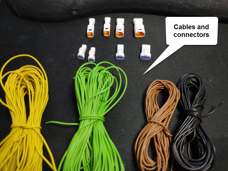
Components
You will need cables for the color
satisfaction brown black green yellow 24AWG you can use up to 26AWG but 24AWG
its ok
You will need 2 meters from each
color
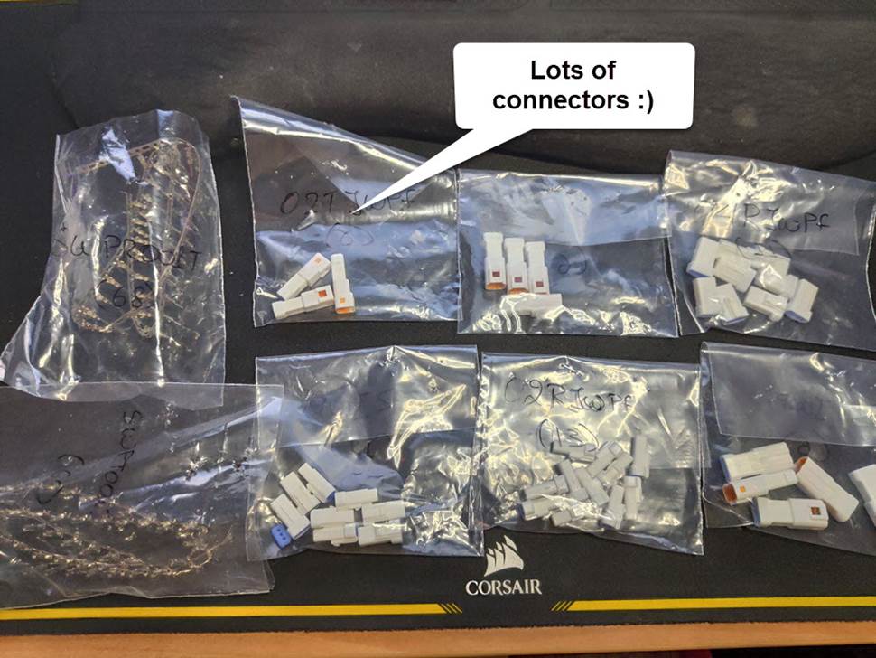
You need to get JWPF Connectors
For the front indicator Left and
Right you will need 2 pairs of
02T-JWPF-VSLE-S (MALE)
02R-JWPF-VSLE-S (FEMALE)
For the rear indicators there is one
connector with 4 cables so you will need 1 pair of
04T-JWPF-VSLE-S (MALE)
04R-JWPF-VSLE-S (FEMALE)
For getting power for the device you
will need to get it from the stop light connector so you will need 1 pair of
03T-JWPF-VSLE-S (MALE)
03R-JWPF-VSLE-S (FEMALE)
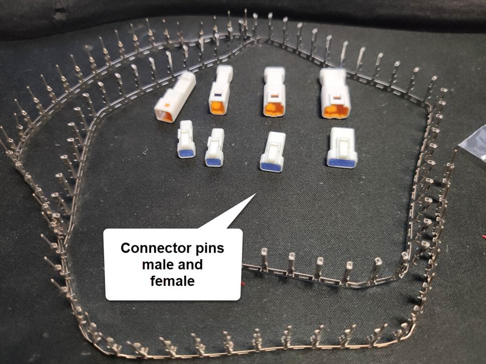
You will also need the male and female pins for
the connectors
11 x SWPT-001T-P025
11 X SWPR-001T-P025
I suggest you get some
spare for the connectors because it’s a little tricky to cable it correct
Main device this is the magic box
You will need a 12V Relay circuit with Delay
timer 😊
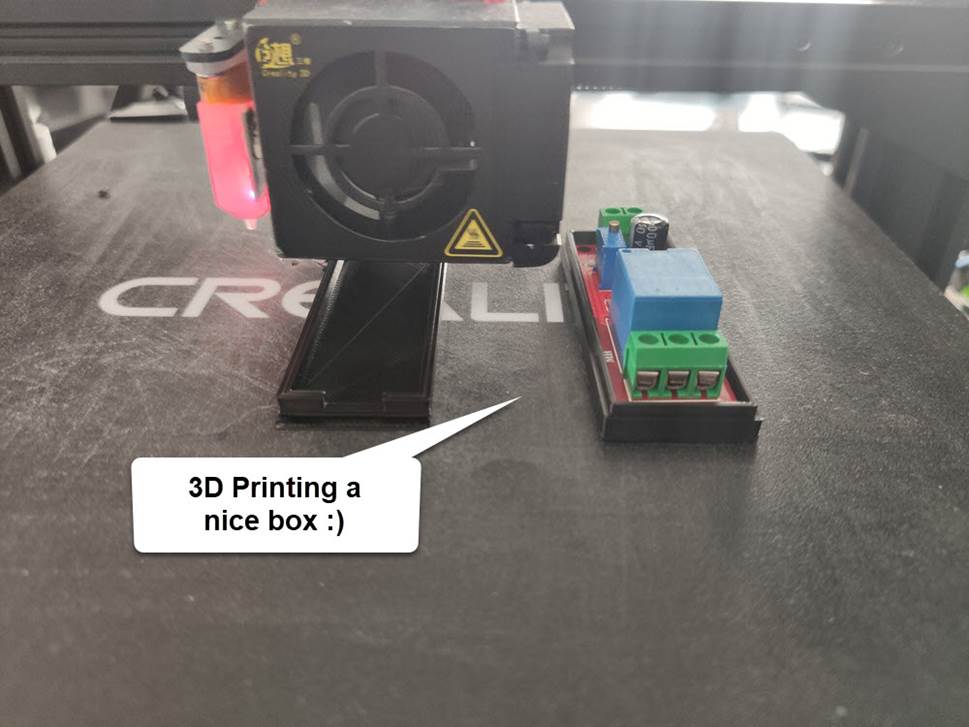
Finally, you will need wire tubing and heat
shrink tubing and a nice little box to install the circuit.
I print mine 😊
Components
Photos
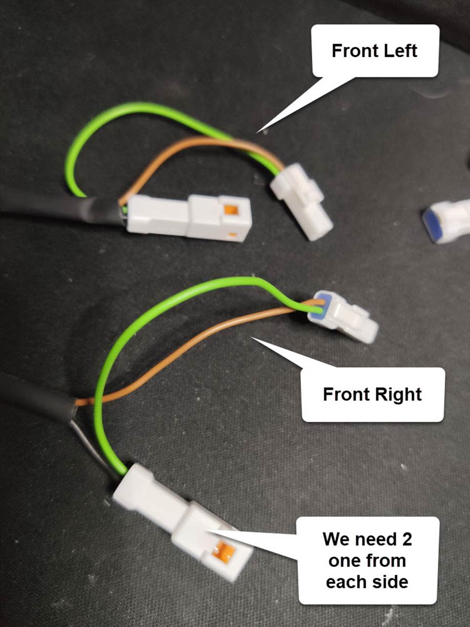
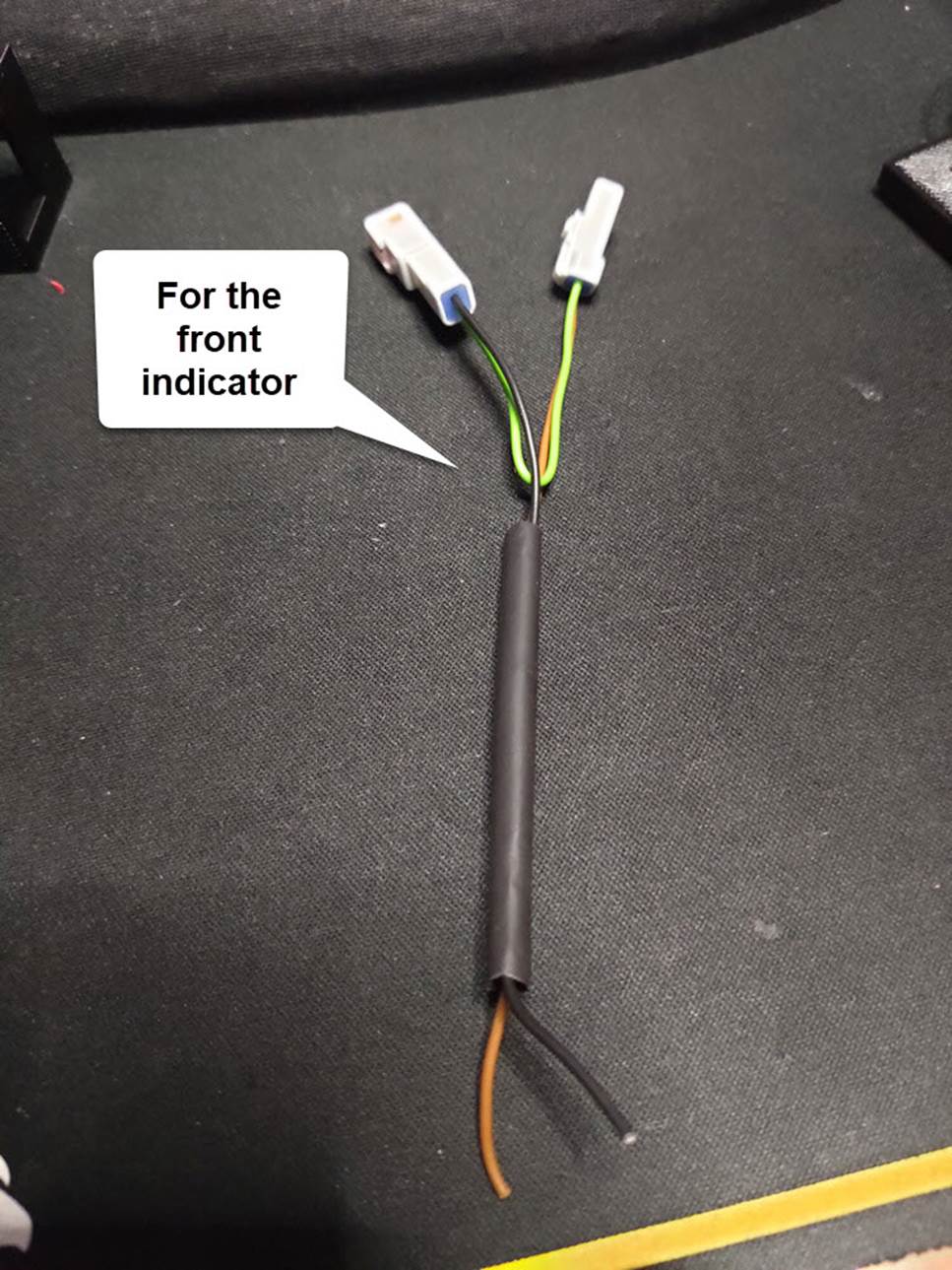
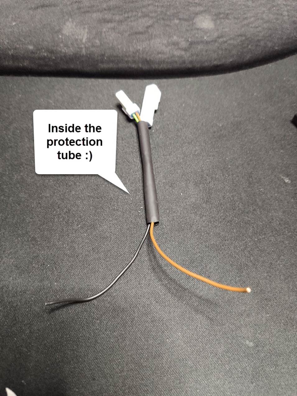
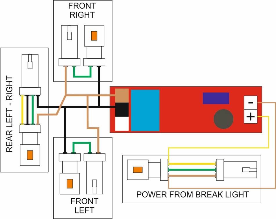
Let’s
create the front connectors
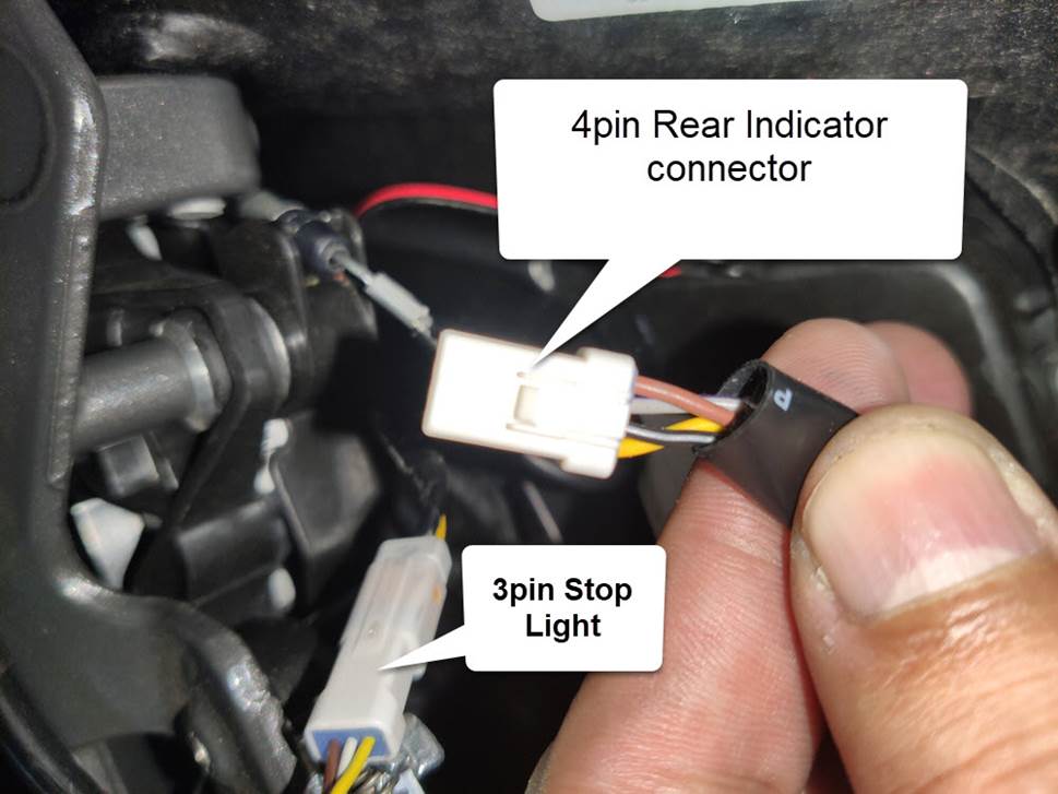
Let’s
create the rear indicator connector
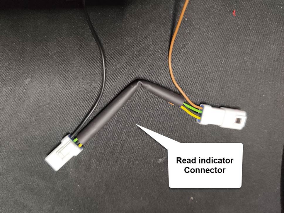
You need to create a straight true cable
connector the only cable you will use is the brawn
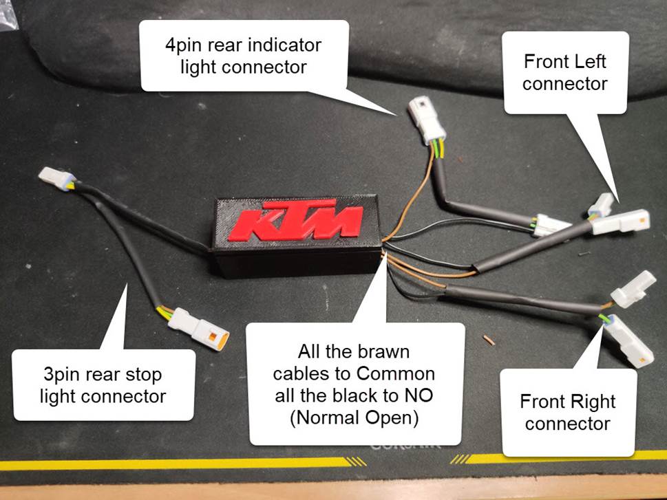
Magic
Box (I just name it like this)
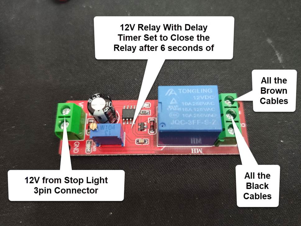
You can get one of this really easy and cheap
the circuit its very simple
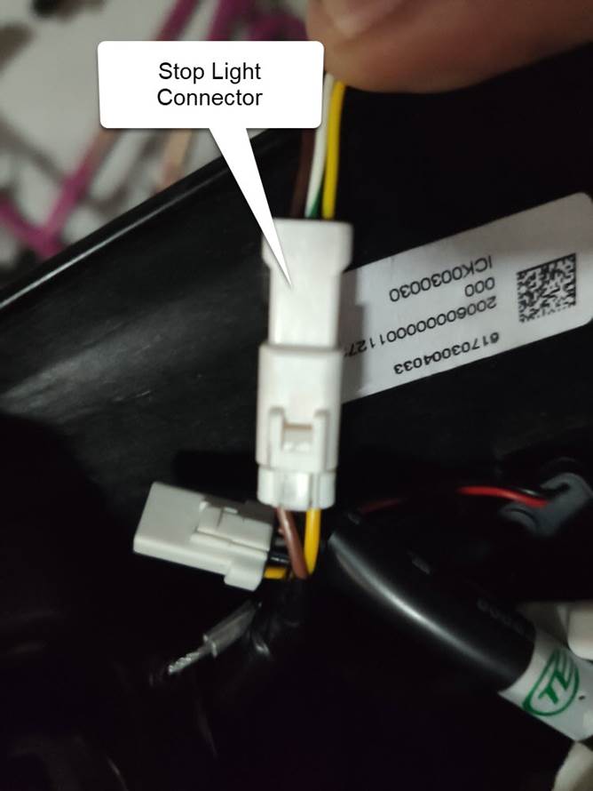
Let’s
create the power connector for our magic box
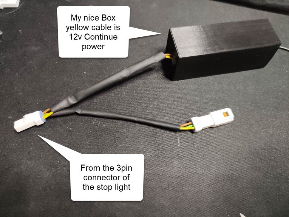
With this connection you get the power you need
12v for the magic box
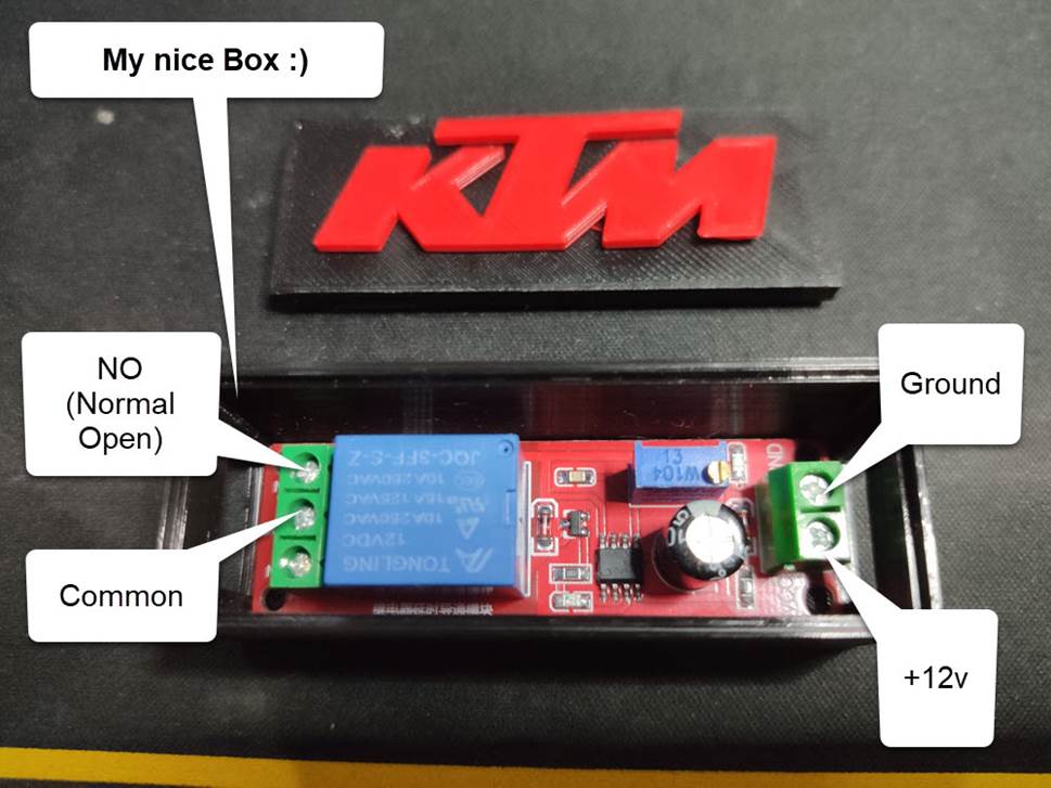
Let’s
create a nice box
1. You must remove the tank cover.
2.Remove the Left and Right sides of the bike.
3. Remove rear seat and driver’s seat
4. The cabling must be pass thru the left side
of the bike for the front left and right connectors
5. You will find the indicator connectors
unplugged if you have the Akrapovic exhaust installed
Right Side of the Bike the blue tube is the
line that goes to the back of the bike.
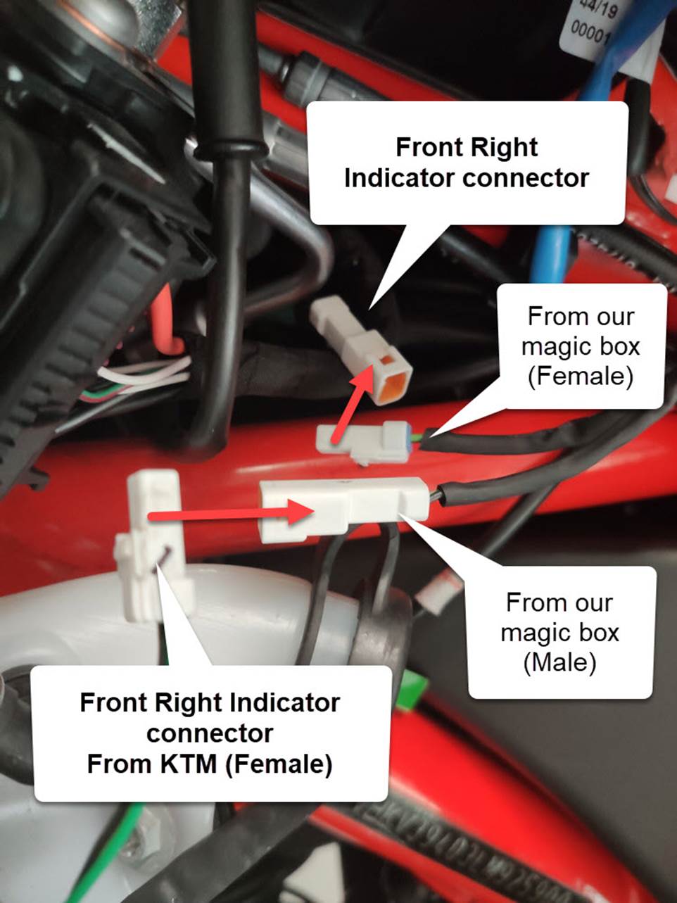
6. Connect the bike connectors with the magic
box connectors do the same for the left side
Rear
Connection of the Magic box
This
is the full connection
 3
3
and here is the links for the 3D Printer files
(STL) 3 pcs 1 for bottom 1 for cover 1 for logo :)
http://systemnet.gr/magicbox/box_bottom.stl
http://systemnet.gr/magicbox/box_cover.stl
http://systemnet.gr/magicbox/box_logo.stl